当然可以!这是按要求的英文和中文段落交替格式:
Experiment 5 Interferometer
1 Purpose
In this experiment, you will use an interferometer base designed to be used in Michelson or Fabry-Perot mode. In the first part of the experiment, you will set up the device to obtain two separate measurements of the wavelength of a He-Ne laser. Once you have determined the wavelength of the laser, you will measure the indices of refraction of air.
在本实验中,您将使用一个干涉仪基础装置,该装置设计为可用于迈克耳孙或法布里-佩罗模式。在实验的第一部分,您将设置设备以分别测量氦氖激光的波长。确定激光波长后,您将测量空气的折射率。
-
CAUTION: Handle all vacuum cells, mirrors and lenses at the sides to prevent fingerprints. Lenses and mirrors with fingerprints can affect the result of your experiment.
-
CAUTION: Prior to turning the laser on, check all mirrors and lenses to make sure they are free from fingerprints. If there are fingerprints, wipe them off with isopropyl alcohol and the provided dry wipes.
-
警告:在处理所有真空室、镜子和透镜时,请从侧面拿取,以防止留下指纹。带有指纹的透镜和镜子可能会影响实验结果。
-
警告:在开启激光之前,请检查所有镜子和透镜,确保它们没有指纹。如果有指纹,请使用异丙醇和提供的干擦布擦拭掉。
2 Introduction
An interferometer is a device that splits a beam of light into several parts and then recombines them to form an interference pattern. The pattern can be used to measure the wavelength of the light (or other lengths) with tremendous accuracy. By interference, we naturally mean the behavior of waves when they superimpose. When two waves encounter each other, the resulting wave is the sum of the two individual waves. Interference can be totally constructive, totally destructive, or a combination of both (see Fig. 5.1). The amount depends on the relative phases of the component waves.
干涉仪是一种将光束分成几部分,然后再将它们重新组合以形成干涉图案的设备。这个图案可以用来以极高的精度测量光的波长(或其他长度)。在干涉中,我们自然指的是波在重叠时的行为。当两波相遇时,结果波是两波的和。干涉可以是完全建构性干涉、完全破坏性干涉,或者是两者的组合(见图 5.1)。干涉的程度取决于组成波的相对相位。
3 Fabry-Perot Interferometer
In a Fabry-Perot Interferometer, two partial mirrors are aligned parallel to one another, forming a reflective cavity. Figure 5.2 shows one ray of light entering such a cavity and reflecting back and forth inside. At each reflection, part of the beam is transmitted, splitting each incident ray into a series of rays. Since the transmitted rays are all split from a single incident ray, they have a constant phase relationship (assuming a sufficiently coherent light source is used).
在法布里-佩罗干涉仪中,两个部分镜子平行对准,形成一个反射腔。图 5.2显示了一束光进入这样的腔体并在其中来回反射。在每次反射时,部分光束会透过,分裂每条入射光线为一系列光线。由于透过的光线都来自同一入射光线,它们具有恒定的相位关系(假设使用的是足够相干的光源)。
The phase relationship between the transmitted rays depends on the angle at which each ray enters the cavity and on the distance between the two mirrors. The result is a circular fringe pattern, with fringes that are thin, bright, and more widely spaced. An example of this pattern is depicted in Fig. 5.3. The sharpness of the Fabry-Perot fringes makes it a valuable tool in high resolution spectrometry. Moving one of the mirrors will change the distance (and thus phase relationship) between rays and will cause the fringe pattern to shift. When the movable mirror translates by a distance , the new fringe pattern is identical to the original:
透过光线之间的相位关系取决于每条光线进入腔体的角度以及两个镜子之间的距离。结果是一个圆形干涉条纹图案,其中的条纹既细又亮,并且间距较大。此图案的示例见图 5.3。法布里-佩罗条纹的清晰度使其成为高分辨率光谱学中的有价值工具。移动其中一面镜子会改变光线之间的距离(从而改变相位关系),并会使条纹图案发生偏移。当可动镜子平移一个距离 时,新的条纹图案与原始条纹图案相同:
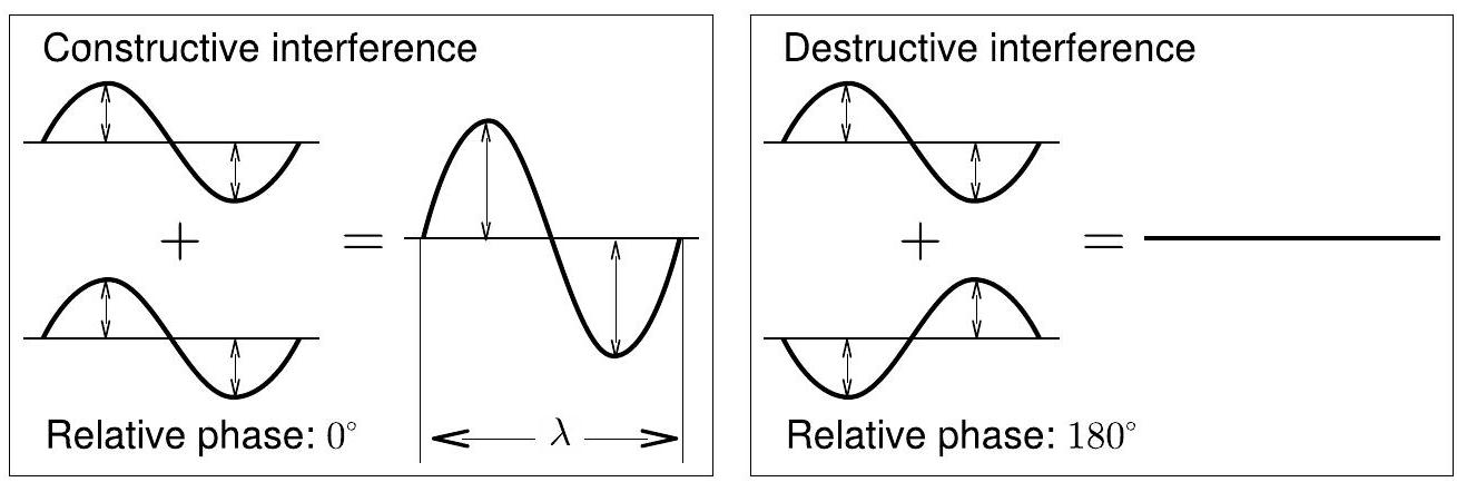
图 5.1:两波的完全建构性和完全破坏性干涉。
4 Michelson Interferometer
A.A. Michelson designed and built the interferometer in 1881 to test for the existence of the "ether," a hypothesized medium through which light was believed to propagate, like waves in water . Today, the Michelson interferometer is used for a number of tasks, including measurements of the wavelength of light, measurements of extremely small distances, and for investigating optical media. The most well-known version is a 3-mile-long version called the Laser Interferometer Gravitational-Wave Observatory (LIGO), used to detect gravitational waves (the co-founders won the 2016 Nobel Prize in Physics!).
A.A. 迈克耳孙于1881年设计并建造了干涉仪,用来检验“以太”的存在,这是一种假设的介质,人们认为光通过它传播,就像水中的波一样。如今,迈克耳孙干涉仪用于许多任务,包括测量光的波长、测量极小的距离以及研究光学介质。最著名的版本是一个长达3英里的版本,叫做激光干涉引力波天文台(LIGO),用于探测引力波(联合创始人获得了2016年诺贝尔物理学奖!)
Figure 5.4 shows a diagram of a Michelson interferometer. A ray of light from the laser strikes a beam splitter, which reflects of the incident light and transmits the other . The incident beam is therefore split into two beams: one transmitted toward a movable mirror , and another reflected toward a fixed-position, adjustable-angle mirror . Both mirrors reflect the light directly back toward the beam splitter. Half the light from is reflected from the beam splitter to the viewing screen, and half the light from is transmitted through the beam splitter to the viewing screen, where it interferes with the light from .
图 5.4 显示了一个迈克耳孙干涉仪的示意图。一束来自激光的光线撞击一个光束分离器,分离器反射50%的入射光并透射另外50%。因此,入射光束被分成两束光束:一束传向可动镜子 ,另一束反射向固定位置、可调角度的镜子 。两面镜子将光线直接反射回光束分离器。来自的光线一部分从光束分离器反射到观察屏,来自的光线一部分透过光束分离器到达观察屏,在那里与来自的光线发生干涉。
Since the two interfering beams of light were split from the same initial beam, they were initially in phase. Their relative phase when they meet at any point on the viewing screen therefore depends only on the difference in the lengths of their optical paths.
由于这两束干涉光束来自同一初始光束,它们最初是同相的。因此,当它们在观察屏的某一点相遇时,它们的相对相位仅取决于它们的光学路径长度差 。
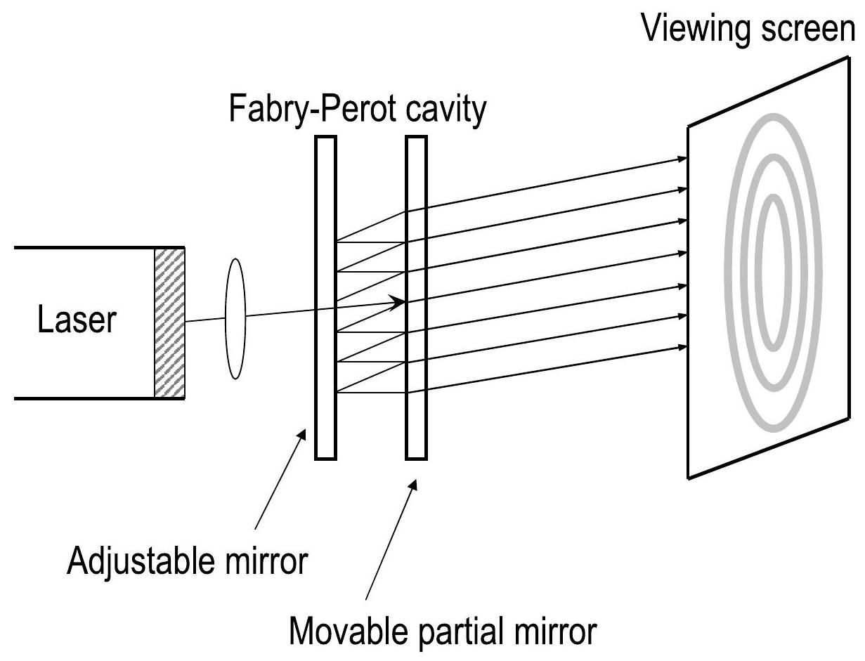
图 5.2:法布里-佩罗干涉仪的示意图。该设备使用一个腔体将每条光线分成一系列光束。(请注意,为了清晰,腔体中的反射有所偏移。)
Convince yourself of the following:
- By moving , the path length of one of the beams can be varied.
- Moving by (a quarter wavelength) closer to the beam splitter will reduce the overall optical path of that beam by .
- Moving will cause the interference pattern on the screen to change
通过以下方式验证:
- 通过移动,可以改变其中一束光束的路径长度。
- 将移动(四分之一波长)靠近光束分离器,将减少该光束的总光学路径长度。
- 移动将导致屏幕上的干涉图案发生变化。
By slowly moving the mirror a measured distance and counting , the number of times the fringe pattern is restored to its original state, the wavelength of the light can be calculated as
通过缓慢地移动镜子一定的距离 并计数 ,即干涉条纹图案恢复到原始状态的次数,可以计算光的波长 为:
Conversely, if the wavelength is already known, one can reverse the procedure and estimate the change in position . In this manner, the interferometer can be used to measure extremely small distance scales.
反过来,如果波长 已知,可以反向操作并估算位置变化 。通过这种方式,干涉仪可以用来测量极小的距离尺度。
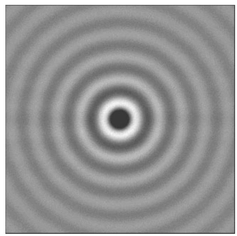
Figure 5.3: Example of the fringe-like interference pattern generated by an interferometer.
图 5.3:干涉仪生成的类似条纹的干涉图案示例。
Here is your content with each paragraph's English terms in bold and the corresponding Chinese translation right after each paragraph. The formulas and symbols are not bolded, and I have kept the image references as is.
5 Index of Refraction of Air
5.1 Introduction
In the Michelson interferometer, the characteristics of the fringe pattern depend on the phase relationship between the two interfering beams. There are two ways to change this phase relationship: the first is to change the distance traveled by one or both beams (by moving the movable mirror, for example); and the second is to change the medium through which one or both of the beams pass. This second method can be used to measure the index of refraction of air.
在迈克耳孙干涉仪中,干涉条纹的特征取决于两束干涉光束之间的相位关系。改变这一相位关系有两种方法:第一种是改变一束或两束光束所经过的距离(例如通过移动可动镜);第二种是改变其中一束或两束光束通过的介质。第二种方法可用于测量空气的折射率。
When light travels through some medium, its wavelength varies according to the formula
where is the wavelength of the light in vacuum and is the index of refraction of the medium. For reasonably low pressures, the index of refraction for a gas varies linearly with the gas pressure. As the index of refraction varies, so does the wavelength in the medium.
当光通过某种介质时,其波长 根据公式变化:
其中, 是光在真空中的波长, 是该介质的折射率。在合理低的压力下,气体的折射率与气体压力呈线性关系。随着折射率的变化,介质中的波长 也会发生变化。
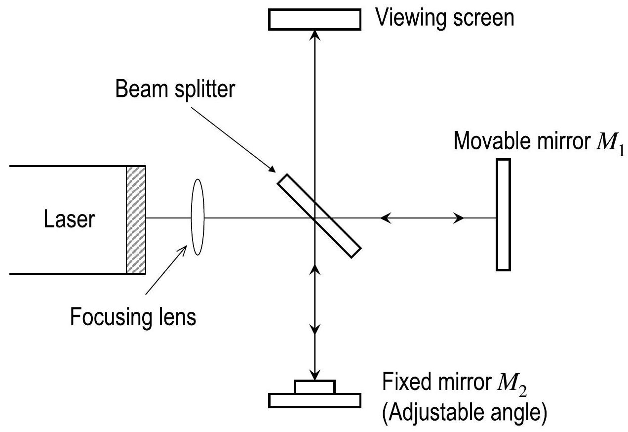
Figure 5.4: Diagram of the Michelson interferometer. A single beam is split into two rays by a half-silvered mirror. The path difference between the rays is varied with a movable mirror.
图5.4:迈克耳孙干涉仪示意图。一束光束通过半银化镜分成两束光线,两束光线之间的路径差通过可动镜变化。
5.2 Pressure and Changing Index of Refraction of Air
You will find by placing a vacuum cell along one leg of the Michelson interferometer. As you pump air out of the cell, the wavelength of the light inside will increase relative to that outside. This causes a shift in the interference pattern.
通过将真空单元放置在迈克耳孙干涉仪的一条腿上,你可以找出 。当你把空气抽出单元时,光在单元内的波长相对于外部的波长增大。这会导致干涉图样的变化。
Originally there are wavelengths of light within the cell (considering that the laser beam passes through the cell twice, on the forward and return trip). At the final pressure there are wavelengths within the cell. The difference between these values is equal to the number of fringes you might observe. Therefore, , or
最初,单元内有 个光波长(考虑到激光束通过单元两次,前行和返回时)。在最终压力下,单元内有 个光波长。这些值之间的差值等于你可能观察到的干涉条纹的数量。因此,,或者:
Vacuum cell
真空单元
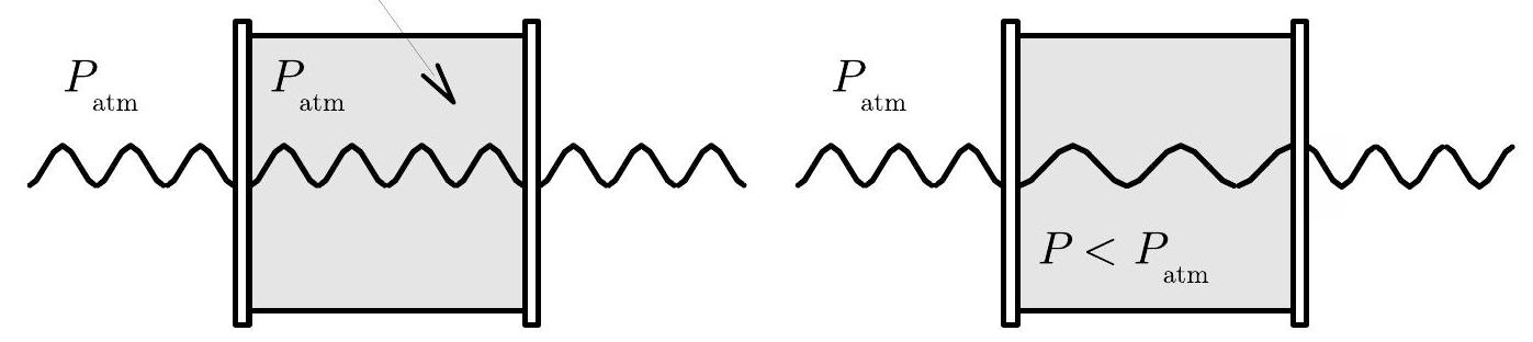
Figure 5.5: Shift in the wavelength of light in the vacuum cell when air is pumped out.
图5.5:当空气被抽出时,真空单元中光波长的变化。
6 Experiment
6.1 Laser Setup
Prior to starting
CAUTION: Handle all vacuum cells, mirrors and lenses at the sides to prevent fingerprints. Lenses and mirrors with fingerprints can affect the result of your experiment.
CAUTION: Prior to turning the laser on, check all mirrors and lenses to make sure they are free from fingerprints. If there are fingerprints, wipe them off with isopropyl alcohol and the provided dry wipes.
实验前
警告:处理所有的真空单元、镜子和透镜时请从侧面拿取,以防留下指纹。有指纹的透镜和镜子可能会影响实验结果。
警告:在打开激光器之前,请检查所有镜子和透镜,确保它们没有指纹。如果有指纹,请用异丙醇和提供的干湿纸巾擦拭。
Here is the content with the English terms bolded in each paragraph, and the corresponding Chinese translation immediately after each paragraph, as requested:
Set the interferometer base on a lab table with the micrometer knob pointing toward you.
将干涉仪基座放置在实验台上,千分尺旋钮朝向你。
Position the laser alignment bench to the left of the base, approximately perpendicular to the interferometer base, and place the laser on the bench.
将激光对准台放置在基座的左侧,约与干涉仪基座垂直,并将激光器放置在对准台上。
Secure one of the component holders (52-54) on the left side of the interferometer base, and another on the right side, both facing in.
将一个组件支架(52-54)固定在干涉仪基座的左侧,另一个固定在右侧,两个支架都朝内。
Turn the laser on. Using the leveling screws on the laser bench, adjust its height until the laser beam passes through the center of both component holders. (Use a piece of paper to check the beam path.) You may need to shift the laser bench slightly in order to adjust the horizontal path of the laser as well. This is most easily done by gently sliding the rear end of the laser transverse to the axis of the alignment bench.
打开激光器。使用激光台上的调平螺丝调整激光台的高度,直到激光束通过两个组件支架的中心。(可以用纸检查光束路径。)你可能需要稍微移动激光台,以调整激光器的水平路径。这可以通过轻轻地滑动激光器的后端来实现,使其与对准台的轴线垂直。
Place the movable mirror (58) in the recessed hole on the interferometer base.
将可动镜(58)放置在干涉仪基座上的凹槽中。
Check that the beam is reflected back from the movable mirror close to the laser aperture, and secure the mirror. (If it isn't, you may need to make small adjustments to the position of the movable mirror, and/or the alignment of the laser, until it is.) You are now ready to set up the interferometer in any of its modes of operation.
检查光束是否从可动镜反射回到接近激光孔径的位置,并固定镜子。(如果没有,你可能需要对可动镜的位置和/或激光器的对准进行微调,直到正确为止。)现在,你已准备好以任何工作模式设置干涉仪。
6.2 Measurement of Laser Wavelength (in Fabry-Perot Mode)
The Fabry-Perot interferometer is only used once, at the start of the lab, to measure the wavelength of the laser light.
法布里-佩罗干涉仪仅在实验开始时使用一次,用于测量激光光的波长。
-
Align the laser and interferometer base as described in the Laser subsection above.
-
Mount the adjustable mirror (51) on the interferometer base in Fabry-Perot position, facing the movable mirror.
-
Place the viewing screen (62) on the component holder behind the movable mirror using its magnetic backing. You should see several images of the laser beam on the viewing screen.
-
Using the thumbscrews, adjust the tilt of the adjustable mirror until there is only one bright dot on the screen.
-
Attach the 18 mm FL lens to the magnetic backing of the component holder in front of the laser, so that the lens is on the side of the component holder furthest from the laser. Adjust the position of the lens until the diverging beam is centered on the adjustable mirror. A clear sharp interference pattern should be visible on the viewing screen.
-
如上文所述,按激光器小节中的方法对准激光器和干涉仪基座。
-
将可调镜(51)安装在干涉仪基座上,并调整至法布里-佩罗位置,面对可动镜。
-
使用其磁性支撑将观察屏(62)放置在可动镜后面的组件支架上。你应该能在观察屏上看到几幅激光束的图像。
-
使用拇指螺丝调整可调镜的倾斜度,直到屏幕上只显示一个亮点。
-
将18 mm 焦距镜头 固定在激光器前方组件支架的磁性支撑上,使镜头位于组件支架远离激光器的一侧。调整镜头的位置,直到发散的光束居中于可调镜。此时,观察屏上应该可以看到一个清晰的干涉图样。
当然可以!以下是按照您的要求进行英文和中文段落交替的格式:
Now you are ready to measure the wavelength of the laser.
现在,您准备好测量激光的波长。
-
Adjust the micrometer knob to a middle reading (approximately ). In this position, the relationship between the micrometer reading and the mirror movement is most nearly linear.
-
Turn the micrometer knob one full turn counterclockwise. Continue turning counterclockwise until the zero on the knob is aligned with the index mark. Record the micrometer reading.
-
Adjust the position of the viewing screen so that one of the marks on the millimeter scale is aligned with one of the fringes in your interference pattern. You may find it easier to count the fringes if the reference mark is one or two fringes out from the center of the pattern, or you may find that counting "bullseyes" is easier.
-
Rotate the micrometer knob slowly counterclockwise. Count the fringes as they pass your reference mark. Continue until some predetermined number of fringes (at least 20) have passed your mark. As you finish your count, the fringes should be in the same position with respect to your reference mark as they were when you started to count. Record the final reading of the micrometer dial.
-
Record , the distance that the movable mirror moved toward the beam splitter according to your readings of the micrometer knob. Remember, each small division on the micrometer knob corresponds to of mirror movement.
-
Record , the number of fringe transitions that you counted.
-
Repeat the above steps for a total of 5 trials, recording your results each time.
-
将千分尺旋钮调整到中间读数(大约)。在此位置,千分尺读数与镜子运动之间的关系最接近线性。
-
将千分尺旋钮逆时针旋转一整圈。继续逆时针旋转,直到旋钮上的零点与标记对齐。记录千分尺读数。
-
调整观察屏的位置,使毫米刻度上的一个标记与干涉图案中的一个条纹对齐。如果参考标记距图案中心一到两个条纹,您可能会发现更容易数条纹,或者您也可以使用数靶心的方式。
-
慢慢地逆时针旋转千分尺旋钮。当条纹经过参考标记时,数一下它们。继续数,直到有预定数量的条纹(至少20个)通过您的标记。完成计数时,条纹应该与开始计数时的位置相同。记录千分尺表盘的最终读数。
-
记录 ,即根据千分尺旋钮读数记录的可动镜子向光束分离器移动的距离。记住,千分尺旋钮上的每个小刻度对应于的镜子运动。
-
记录 ,即您计数的条纹过渡次数。
-
对以上步骤进行5次重复试验,每次记录结果。
6.3 Measurement of Laser Wavelength (in Michelson Mode)
6.3 激光波长的测量(迈克耳孙模式)
-
Remove the 18 mm FL lens .
-
Mount the adjustable mirror on the interferometer base in Michelson position. Place the second component holder opposite the adjustable mirror and attach the viewing screen to its magnetic backing.
-
Position the beam splitter (55) at a angle to the laser beam, within the crop marks, so that the beam is reflected to the adjustable mirror. Adjust the angle of the beam splitter as needed so that the reflected beam hits the adjustable mirror near its center.
-
There should now be two sets of bright dots on the viewing screen; one set comes from the fixed mirror and the other comes from the movable mirror. Each set of dots should include a bright dot with two more dots of lesser brightness (due to multiple reflections). Adjust the angle of the beam splitter again until the two sets of dots are as close together as possible, then tighten the thumbscrew to secure the beam splitter.
-
Using the thumbscrews on the back of the adjustable mirror, adjust the mirror's tilt until the two sets of dots on the viewing screen coincide.
-
Attach the 18 mm FL lens to the magnetic backing of the component holder in front of the laser such that the lens is on the side of the component holder furthest from the laser. Adjust the position of the lens until the diverging beam is centered on the beam splitter. You should now see circular fringes on the viewing screen. If not, carefully adjust the tilt of the adjustable mirror until the fringes appear.
-
移除18毫米焦距透镜 。
-
将可调镜子安装在干涉仪基础上,处于迈克耳孙位置。将第二个组件支架放置在可调镜子对面,并将观察屏安装在其磁性支架上。
-
将光束分离器(55)放置在激光光束的角度内,位于裁剪标记内,使得光束被反射到可调镜子。根据需要调整光束分离器的角度,使得反射的光束接近可调镜子的中心。
-
现在,观察屏上应有两组明亮的点;一组来自固定镜子,另一组来自可动镜子。每组点应包括一个明亮点和两个较暗的点(由于多次反射)。再次调整光束分离器的角度,直到两组点尽可能接近,然后紧固拇指螺钉以固定光束分离器。
-
使用可调镜子背面的拇指螺钉,调整镜子的倾斜,直到观察屏上的两组点重合。
-
将18毫米焦距透镜 安装在激光前组件支架的磁性支架上,使透镜位于组件支架最远离激光的一侧。调整透镜的位置,直到发散的光束与光束分离器对齐。现在,您应能在观察屏上看到圆形条纹。如果没有,请小心调整可调镜子的倾斜角度,直到条纹出现。
You will now repeat the measurement of the laser wavelength that you performed with the Fabry-Perot setup, which you can refer to on page 55.
您现在将重复您在法布里-佩罗设置中进行的激光波长测量,您可以参考第55页的说明。
-
Record , the number of fringe transitions that you counted, and the final position on the micrometer knob, for 5 trials.
-
记录 ,即您计数的条纹过渡次数,以及千分尺旋钮上的最终位置,共进行5次试验。
6.4 Measuring the Index of Refraction of Air
To measure , the index of refraction of air, we will pump air out of a vacuum cell and measure the change in the number of fringes, , for some pressure change . Once you know how changes in pressure affect the index of refraction, you can determine , the index of refraction of air, knowing , , and . As we pump air out of the chamber, two things will happen:
要测量 ,空气的折射率,我们将把空气从真空室中抽出,并测量条纹数量 随着某一压力变化 的变化。一旦了解压力变化如何影响折射率,我们可以通过已知 、 和 来确定 ,空气的折射率。当我们从腔体中抽出空气时,会发生以下两件事:
-
Pressure inside the cell drops
-
The refractive index, , reduces. Recall that the refractive index of absolute vacuum is defined to be .
-
真空室中的压力下降
-
折射率 减小。回想一下,绝对真空的折射率定义为 。
Dividing both sides of equation (5.2) by , we get
将方程 (5.2) 两边除以 ,得到:
The quantity on the left side is the slope of an vs. graph. Since we assume that the index of refraction varies linearly with pressure (at low pressures), this ratio is constant for any corresponding difference between and . Thus, we can rewrite the formula as a linear equation.
左边的量是 与 图的斜率。由于我们假设折射率与压力(在低压力下)线性变化,因此对于任何折射率与压力之间的差异,这个比值是常数。因此,我们可以将公式重写为线性方程:
where is a constant that will be experimentally determined. Since the left-hand side is constant, the quantity on the right-hand side of the equation is also a constant.
其中 是一个将通过实验确定的常数。由于左边是常数,因此方程右边的量也是常数。
-
Align the laser and interferometer in Michelson mode.
-
Place the rotational pointer between the movable mirror and the beam splitter.
-
Attach the vacuum cell to its magnetic backing and push the air hose of the vacuum pump over the air outlet hole of the cell.
-
Adjust the alignment of the fixed mirror as needed so the center of the interference patterns is clearly visible on the viewing screen. The fringe pattern will be somewhat distorted by irregularities in the glass end-plates of the vacuum cell, but this is not a major concern.
-
For accurate measurements, the end-plates of the vacuum cell must be perpendicular to the laser beam. Rotate the cell and observe the fringes. Based on your observations, how can you be sure that the vacuum cell is properly aligned?
-
将激光器和干涉仪调整至迈克耳孙模式。
-
将旋转指针放置在可动镜子和光束分离器之间。
-
将真空室附着到其磁性支架上,并将真空泵的空气管插入真空室的空气出口孔中。
-
根据需要调整固定镜子的对准,使干涉图案的中心在观察屏上清晰可见。条纹图案会因真空室中玻璃端板的不规则性而略微扭曲,但这不是主要问题。
-
为了进行准确测量,真空室的端板必须与激光光束垂直。旋转真空室并观察条纹。根据您的观察,您如何确保真空室正确对准?
Now you are ready to measure the wavelength of the laser.
现在,您准备好测量激光的波长。
-
To collect data for fringe number count as the pressure in the cell changes, begin with a cell at atmospheric pressure.
-
Slowly pump on the handle which will evacuate air from the cell and record the number of fringes, , that have passed during the interval, and the pressure at the end of the interval.
-
Note that the pressure you measure is actually a gauge pressure , since the gauge starts at zero when the cell is at atmospheric pressure. Convert your values to , the number of fringes at a given pressure minus the number of fringes corresponding to atmospheric pressure. (You don't know , the number of fringes corresponding to the cell at atmospheric pressure, but you can determine the number of fringes that have passed since you started evacuating the cell, and this is ). Obtain at least 7 data points for and various .
-
Convert your values for to using eq. (5.2).
-
为了收集条纹数量计数的数据,随着真空室内压力变化,首先使用处于大气压力下的真空室。
-
慢慢转动手柄,排出真空室中的空气,并记录在该时间间隔内通过的条纹数 ,以及该时间间隔结束时的压力 。
-
请注意,您测量的压力实际上是表压 ,因为表压计在真空室处于大气压力时从零开始。当您开始抽空真空室时,您可以计算条纹数的变化,将您的 值转换为 ,即给定压力下的条纹数减去大气压力下对应的条纹数。(您不知道 ,即在大气压力下真空室对应的条纹数,但您可以确定自从开始排气以来已经经过的条纹数,这就是 )。获取至少7个数据点,记录 和不同的 。
-
使用公式 (5.2) 将您的 值转换为 。
当然可以!以下是按照您要求的英文和中文段落交替格式:
6.5 Summary of data:
Fabry-Perot section:
= for 5 runs
6.5 数据总结:
法布里-佩罗部分:
= 经过5次实验
Michelson section:
= for 5 runs
+\Delta P$ for several runs
迈克耳孙部分:
= 经过5次实验
+\Delta P$ 进行若干次实验
7 Advice for Accurate Fringe Counting
- It's not necessary that your interference pattern be perfectly symmetrical or sharp. As long as you can clearly distinguish the maxima and minima, you can make accurate measurements.
- It's easy to lose track when counting fringes. It can help to focus on a fringe a few away from the center, or to use the "disappearing bullseye" technique, in which you observe the central minimum, to count the fringes.
- When turning the micrometer dial to count fringes, always turn it one complete revolution before you start counting, then continue turning it in the same direction while counting. This will almost entirely eliminate errors due to backlash in the micrometer movement. (Backlash is a slight slippage that always occurs when you reverse the direction of motion in a mechanical system.) Turning the micrometer dial clockwise moves the movable mirror toward the right.
- Always take several readings and average them for greater accuracy or have multiple members count the same run and compare results.
- Warm up the laser to reduce intensity and polarization variations.
7 精确条纹计数建议
- 干涉图案不必完全对称或锐利。只要您能清楚地区分最大值和最小值,您就可以进行准确的测量。
- 在计数条纹时容易丢失轨迹。可以将焦点集中在离中心几位的条纹上,或者使用“消失的靶心”技术,通过观察中心最小值来计数条纹。
- 在转动千分尺旋钮计数条纹时,始终在开始计数之前旋转一整圈,然后继续在同一方向转动并计数。这将几乎完全消除由于千分尺运动的反弹所导致的误差。(反弹是指在机械系统中反向运动时,常发生的轻微滑移。)顺时针转动千分尺旋钮会使可动镜子向右移动。
- 总是多次读取并取平均值以提高准确性,或者让多个成员计数同一试验并比较结果。
- 预热激光以减少强度和偏振变化。
8 Analysis
8.1 Laser Wavelength
- For the measurement of the laser wavelength, take your results for the number of fringes moved and the distance traveled by the movable mirror and convert them to a wavelength.
- Average these wavelengths, and find the standard deviation of the mean: .
- Compare the results from the two separate methods. Do they agree within uncertainties? Does one method appear to be more accurate than the other?
8 分析
8.1 激光波长
- 对于激光波长的测量,获取您关于条纹移动的结果 和可动镜子移动的距离 ,并将它们转换为波长。
- 对这些波长取平均值,并求出均值的标准差:。
- 比较两个不同方法的结果。它们在误差范围内一致吗?是否有某种方法看起来比另一种更精确?
8.2 Index of Refraction of Air
- Make a plot of vs. for your data.
- Draw a line of best fit and determine the slope, . This slope is slightly different from the ratio described by eq. (5.3). However, you should be able to convince yourself that changing the and values by a constant, and , shouldn't change the slope at all (these constant values will subtract out when calculating the slope). Therefore, we can use our graph of vs. to determine our constant .
- Once you know the slope of your line, you know the constant value of the right-hand side of eq.(5.4). Now you can plug in values on the left-hand side. Take , the index of refraction of air at atmospheric pressure, to be the unknown value - this is the original pressure in the cell before you pumped the air out.
- For the other three values on the left-hand side you can plug in the atmospheric pressure and the pressure in a vacuum, both in cm Hg, and the index of refraction of a vacuum. This will allow you to calculate the index of refraction in air.
- Compare your value of at atmospheric pressure and standard temperature to that given in a recognized source (e.g., CRC Handbook of Chemistry and Physics). Comment on the results.
8.2 空气的折射率
- 为您的数据绘制 与 的图。
- 绘制最优拟合线并确定其斜率 。此斜率与公式(5.3)中描述的比值略有不同。然而,您应该能够确信通过一个常数 和 改变 和 值,不应改变斜率(这些常数值在计算斜率时会相互抵消)。因此,我们可以使用 与 的图来确定我们的常数 。
- 一旦知道了线的斜率,就可以得出公式(5.4)右边的常数值。现在您可以将左侧的值代入。将 (大气压下的空气折射率)作为未知值——这是在抽出空气之前真空室内的原始压力。
- 对于左侧的其他三个值,您可以代入大气压力和真空中的压力,两者都以cm Hg为单位,并代入真空的折射率。这将使您能够计算出空气中的折射率。
- 将您在大气压力和标准温度下测得的 与公认来源(例如CRC化学与物理手册)中的值进行比较,并评论结果。
8.3 General Questions
- The Michelson interferometer can be used to measure extremely small distance scales. What is the smallest distance scale that can be measured? What uncertainty is associated with this? How could the precision be increased?
- What is the smallest distance scale that can be measured by the Fabry-Perot interferometer? Which is better, the Michelson or the Fabry-Perot? Why?
- How could you change either of these interferometers to measure smaller distance scales? What if you wanted to use the same equipment as you had in this experiment?
8.3 一般性问题
- 迈克耳孙干涉仪可以用来测量极小的距离尺度。最小的距离尺度是多少?与此相关的不确定性是什么?如何提高精度?
- 法布里-佩罗干涉仪可以测量的最小距离尺度是多少?哪个更好,迈克耳孙还是法布里-佩罗?为什么?
- 您如何修改这些干涉仪来测量更小的距离尺度?如果您想使用您在本次实验中使用的相同设备,该如何做?
[^0]: Michelson's famous experiments discredited the ether hypothesis, hastening the development of Special Relativity.
[^0]: 迈克耳孙的著名实验否定了以太假说,促进了狭义相对论的发展。